M3000 – Electromagnetic Flow Meter

The innovative design of the Badger Meter M-Series M3000 meter represents the next generation of electromagnetic flow meter technology. Incorporating the latest developments in micro processing signal conditioning the advanced design of the M3000 allows an accuracy of better than ± 0.25% with a flow range of 300:1. Targeted to a variety of industrial and municipal applications, the M3000 is virtually unaffected by density, temperature, pressure, and viscosity changes and provides an accurate and reliable long term metering solution. This meter complies with ANSI/NSF Standard 61, Annex G.

Description

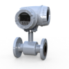
Operation: The operating principle of the electromagnetic flow meter is based on Faraday’s law of magnetic induction: The voltage induced across any conductor, as it moves at right angles through a magnetic field, is proportional to the velocity of that conductor. The voltage induced within the fluid is measured by two diametrically opposed internally mounted electrodes. The induced signal voltage is proportional to the product of the magnetic flux density, the distance between the electrodes and the average flow velocity of the fluid. ELECTRODES When looking from the end of the meter into the inside bore, the two measuring electrodes are positioned at three o’clock and nine o’clock. As a conductive fluid flows through the magnetic field, a voltage is induced across the electrodes. This voltage is proportional to the average flow velocity of the fluid and is measured by the two electrodes. This induced voltage is then amplified and processed digitally by the converter to produce an accurate analog or digital signal. The signal can then be used to indicate flow rate and totalization or to communicate to remote sensors and controllers. M3000 meters also have an “empty pipe” detection feature. This is accomplished with a third electrode positioned in the meter between twelve o’clock and one o’clock. If this electrode is not covered by fluid for minimum of five seconds, the meter will display an “empty pipe” condition. When the electrode again becomes covered with fluid, the error message will disappear and the meter will continue measuring. DETECTOR The flow meter is a stainless steel tube lined with a non-conductive material. Outside the tube, two DC powered electromagnetic coils are positioned opposing each other. Perpendicular to these coils, two electrodes are inserted into the flow tube. Energized coils create a magnetic field across the whole diameter of the pipe. With the no moving parts, open flow tube design there is no pressure lost and practically no maintenance required.

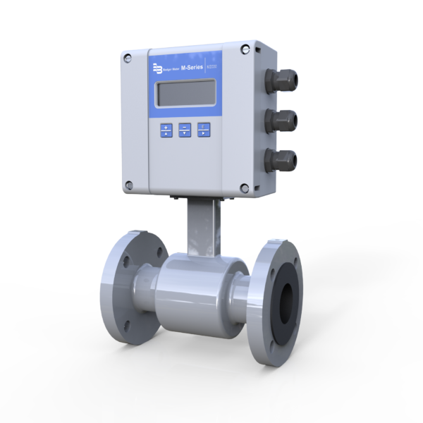
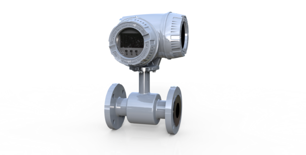
Application: The M3000 is suited for use in applications where indication of rate and totalization is required. The ability to display flow parameters locally at the flow meter, or remotely by mounting the amplifier up to 100 feet away from the detector, provides a versatile solution for most industrial and municipal flow applications. Whether the fluid is water or something highly corrosive, very viscous, contains a moderate amount of solids, or requires special handling, the meter is able to accurately measure it. Housed in a Class 1, Division 2, NEMA 4X/6P (IP66/IP67) enclosure, the M3000 design has been tested and approved by Factory Mutual (FM) in the United States and the Canadian Standards Association (CSA international)  in Canada.

Features:

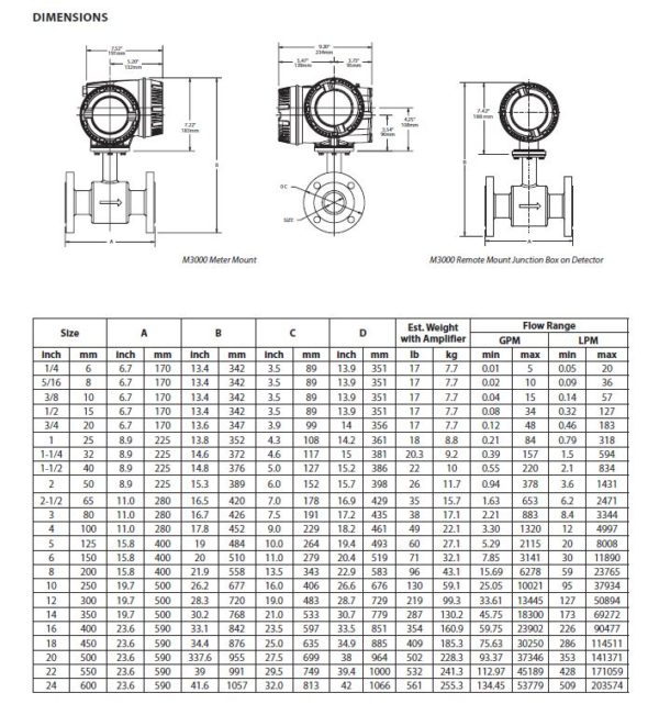
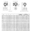
  • Sizes 1/4…24 in. (6…600 mm)
  • Accuracy of ± 0.25%
  • Better than 0.1% repeatability
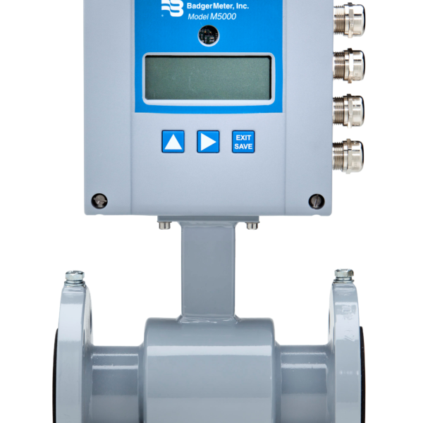
  • Large 4-line by 16-character, back-lit, LCD display
  • Digital Signal Processor (DSP) based
  • Bi-directional flow sensing and totalization
  • Automatic zero point stability
  • Measures fluids with as low as 5.0 micromhos/cm conductivity
  • Empty pipe detection
  • No pressure loss for low operational costs
  • Long life, corrosion-resistant liners
  • Precise calibration
  • NEMA 4X/6P (IP66/IP67) enclosure
  • FM approved for Class I, Div 2 hazardous locations
  • CE and FCC compliant
  • CSA Certified

Additional information

Flow Range

0.10…39.4 ft/s (0.03…12 m/s)

Accuracy

± 0.25 percent of rate for velocities greater than 1.64 ft/s (0.50 m/s) ± 0.004 ft/s (± 1 mm/s) for velocities less than 1.64 ft/s (0.50 m/s)

Repeatability

± 0.1%

Power Supply

AC or optional 24V DC
AC Power Supply: 85…265V AC, 45…65 Hz
Voltage Fluctuation = ± 10% of nominal
Over Voltage = Catagory II
Power Consumption = 20 W
DC Power Supply (optional): 24V DC ± 10% 8 W

Analog Output

0…10 mA, 0…20 mA, 4…20 mA (programmable and scalable)
Voltage sourced (18V DC) isolated
Max. loop resistance = 750 Ω

Digital Output

(2) Open Collector, (programmable – scaled pulse, flow alarm, status, or frequency output) Max. 24V DC, 0.5 W
(2) AC solid-state relay (programmable – flow alarm or status) Max. 24V D C @ 0.5 A

Frequency Output

Open Collector – Max. full scale flow = 10 Khz

Communication

RS232 Modbus RTU; RS485 Modbus RTU, HART, Profibus DP require separate daughterboards

Pulse Width

Open Collector, 5 ms to 1 second (programmable) or automatic 50% duty cycle

Min-Max Flow Alarm

Open collector or solid state relay (programmable, 0 to 100% of flow)

Empty Pipe Detection

Field tunable for optimum performance based on specific application

Excitation Frequency

Programmable, 3.75 Hz, 7.5 Hz or 15 Hz

Low Flow Cut-Off

Programmable 0…100% of maximum flow

Zero-Point Stability

Automatic correction

Galvanic Separation

500V

Fluid Conductivity

Minimum 5.0 micromhos/cm

Fluid Temperature

With Meter-Mounted Amplifier:
PFA, PTFE & Halar®: 4…212° F (20…100° C) @ max. ambient
temperature of 122° F (50° C).
Hard rubber: 32…178° F (0…80° C) @ max. ambient
temperature of 122° F (50° C)

With Remote Amplifier:
PFA, PTFE & Halar: 4…248° F (20…120° C) @ max. ambient
temperature of 122° F (50° C).
Hard rubber: 32…178° F (0…80° C) @ max. ambient
temperature of 122° F (50° C)

Ambient Temperature

– 4…122° F (–20…50° C)

Relative Humidity

Up to 90 percent non-condensing

Altitude

Maximum 6500 ft (2000 m)

Flow Direction

Uni-directional or bi-directional

Totalization

3 separate displayable totalizers – 10 digits (programmable – forward, reverse and net)

Units of Measure

U.S. gallons, imperial gallons, million gallons per day, cubic feet, cubic meters, liters, oil barrels, pounds, ounces, acre feet (programmable)

LC Display

4-line by 16-character, alphanumeric, back light
Displays: 3 totalizer values, flow rate, alarm status, output status, error/diagnostic messages

Programming

Internal 3-button or external magnetic wand

Amplifier Housing

Cast aluminum, powder-coated paint

Amplifier Housing Rating

Amplifier enclosure and remote junction enclosure: NEMA 4X/6P (IP66/IP67)

Detector Pipe Spool Material

316 stainless steel

Detector Spool Housing Material

Carbon steel, welded, NEMA 4X/6P (IP66/IP67)

Electrode Materials

Alloy C, 316 stainless steel (standard), gold/platinum plated, tantalum, platinum/rhodium

Liner Material

PFA from 1/4…3/8 in. (6…10 mm), PTFE from 1/2…24 in. (15…600 mm), hard rubber from 1…24 in. (25…600 mm), Halar from 12…24 in. (300…600 mm)

Flanges

Carbon steel or 316 stainless steel (ANSI B16.5 Class 150 RF)

Coil Power

Pulsed DC

Pressure Limits

Max. 150 psi (10 bar)

Mounting

Direct detector mount or remote wall mount, bracket included. For remote mount, max. cable distance = 100 ft (30 m)

Junction Enclosure Material

For remote mounted amplifier option: Cast aluminum, powder-coated paint, NEMA 4X/6P (IP66/IP67)

Optional Stainless Steel Grounding Rings

Meter Size
1/4…10 in. (6…250 mm)
10…24 in. (250…600 mm)

Thickness (of 1 ring)
0.135 in. (3.43 mm)
0.187 in. (4.75 mm)

Optional Grounding Electrodes

Alloy C, 316 stainless steel, gold/platinum plated, tantalum, or platinum/rhodium

Electrical Classification

FM approved for Class I, Div 2, Groups A-D; Class II, Div 2, Groups F and G, – CSA Certified